Fluids and gases are just as important of a resource as items, but require very different methods of transportation. While there are not as many options, fluid and gas manipulation requires a bit more thought than Item Manipulation.
Fluid and gas are treated mostly the same. The only difference is that gas has infinite Head Lift, meaning it can travel any distance or height without the need for pumps. This page will include both of them as “fluid” when the distinction is not relevant.
Fluids include:
- Water
- Crude Oil
- Heavy Oil Residue
- Fuel
- Turbofuel
- Liquid Biofuel
- Alumina Solution
- Sulfuric Acid
- Nitric Acid
Gases include:
- Nitrogen Gas
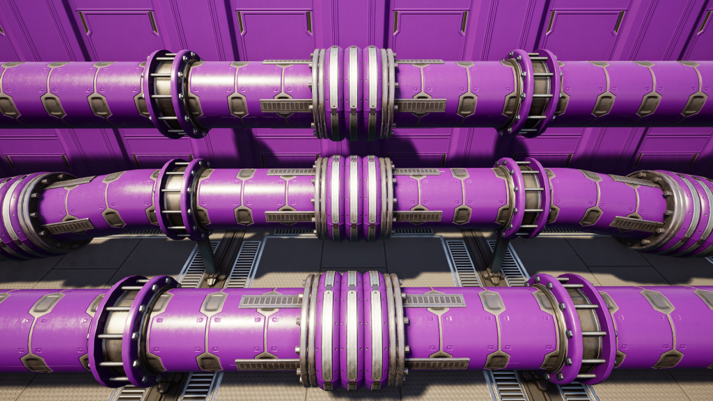
Pipelines
Pipelines are the most basic form of fluid manipulation. Similar to Conveyor Belts, Buildings that use or produce liquids will have an input or output slot to connect a Pipeline.
There are two tiers of Pipelines. The difference between the two is the maximum amount of liquid that can pass through (flow).
| Name | Max Flow Rate (Cubic Meters/Minute) |
|---|---|
| Pipeline Mk.1 | 300 |
| Pipeline Mk.2 | 600 |
Pipelines can be flushed by pulling the lever in their UI. This deletes all Liquid from either the Pipeline Segment or the Full Pipe Network, depending on which option you choose.
Pipeline Junction Cross
Pipeline Junction Crosses allow for both merging and splitting of Pipelines. They have four bi-directional ports. The flow direction for each port is determined by the Head Lift and current volume of the connected Pipeline.
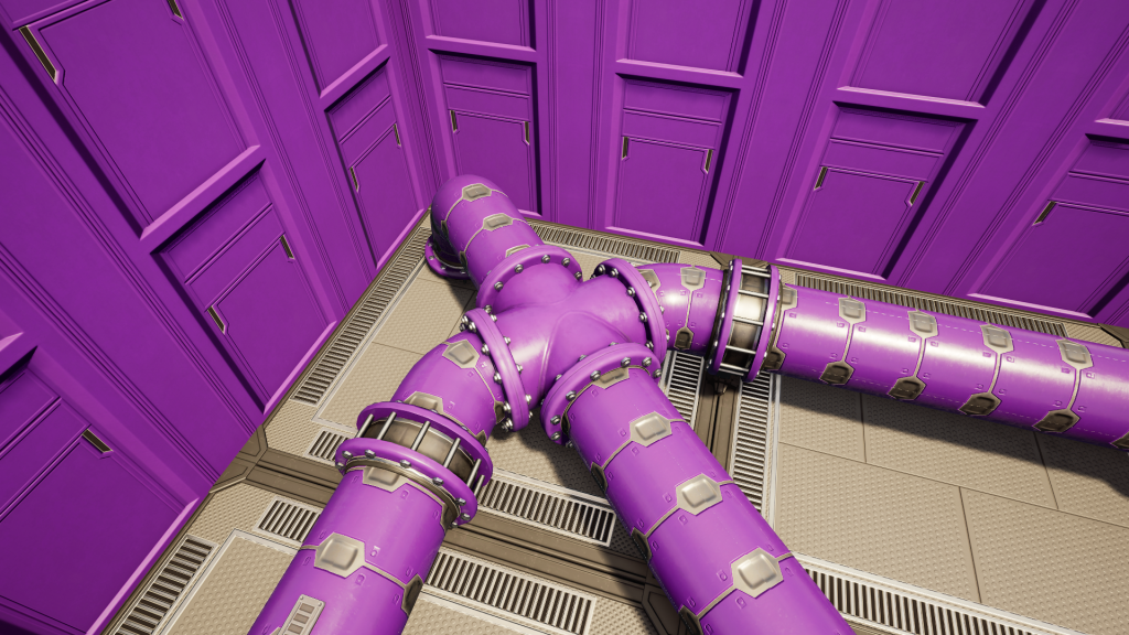
Pipeline Junction Crosses can be built onto the end of Pipelines, into the middle of existing Pipelines, or on their own. They are not configurable in any way and there are currently no “Smart” versions like there are for Conveyor Splitters. However, you can build Valves on each port to help manage flow.
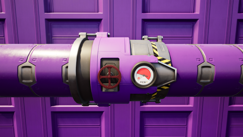
Fluid Flow and Valves
Fluids in Pipes can flow in either direction. In general, Pipelines will try to balance out their volume with neighboring fluid containers. If a Pipeline is more full (percentage wise) than a connected fluid inventory, fluid will flow from that Pipeline to the less full inventory. Alternately, if a Pipeline is connected to a fluid inventory with more (or equal) fluid than itself, fluid will not flow in that direction.
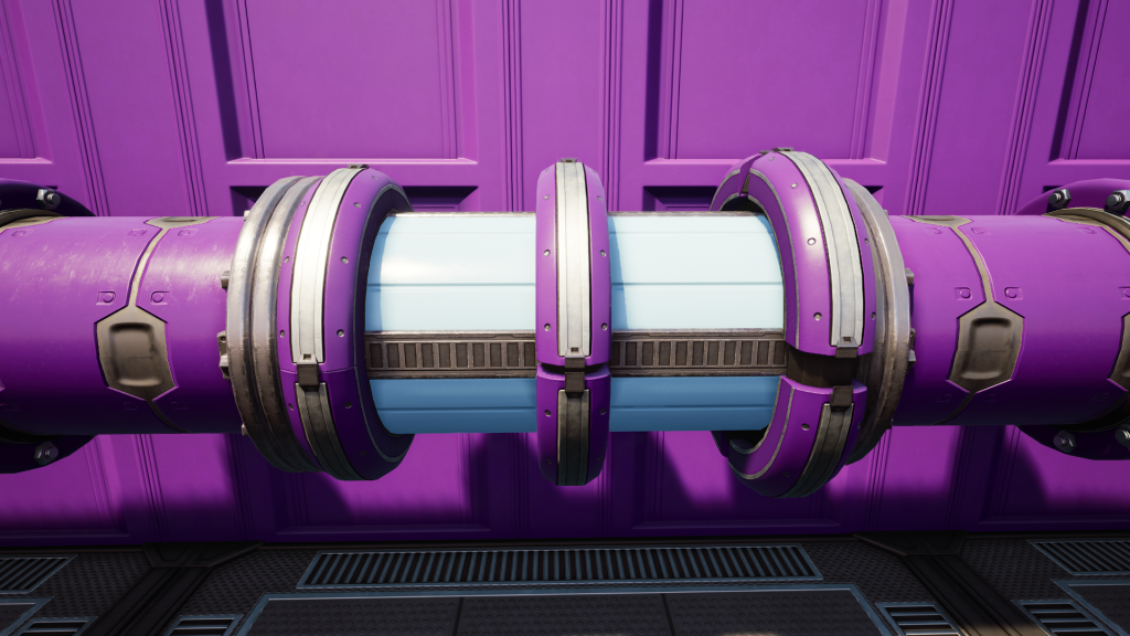
You can see the current flow direction in Pipelines by watching the animation of the three rings in the center of the Pipeline. This indicator will only be present in Pipelines of sufficient length (6m) and is never present on “Clean” Pipelines from the AWESOME Shop.
- Volume – Distance between the rings
- Liquid Type – Color of Pipeline between rings
- Flow Amount – How far each ring expands
- Flow Direction – The animation of the three rings
- The first ring to expand is the direction the liquid is coming from
- The third ring to expand is the direction the liquid is going to
If the input fluid is interrupted, fluid can flow back to balance the volume in the system. Valves can be used to limit flow to only one direction (from the input side to the output side).
A Valve will stop the connected fluid inventory on the output side from considering the fluid inventory on the input side for volume balancing. This means fluids will not flow from the output side to the input side.
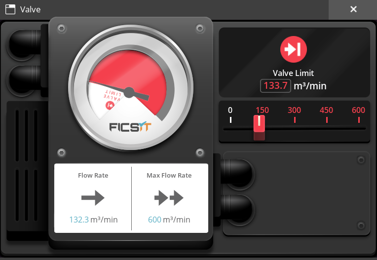
Valves can also be used to limit the flow from the input to the output. Opening the UI of the valve will allow you to set a number between zero (0) and the maximum allowed by the Pipeline (300 or 600).
Precise Valve Flow
For advanced Pioneers looking for perfect fluid precision: while you can type any number into the UI for Valves, there are only a set amount of values that can actually be used.
The coding of the game uses a 7-bit value for flow limit precision (there may be a signed bit for flow direction), meaning there are only 127 options for the flow limit. Each discrete flow setting is a specific fraction of units away from its neighbor.
| Pipeline | Fraction (Exact) |
Decimal (Rounded) |
|---|---|---|
| Pipeline Mk.1 | 300 / 127 | 2.36 |
| Pipeline Mk.2 | 600 / 127 | 4.72 |
When setting a value on the Valve, the game will actually round to the nearest discrete value. Be aware that this rounding can be in either direction, meaning the actual flow rate may be slightly higher OR lower than expected. The true flow rate can be seen once the system starts up.
Head Lift and Pumps
Fluid requires Head Lift (pressure) to move through vertically up Pipes. Most buildings produce some Head Lift from their output ports (10m).
Fluid does not fill empty pipes instantly. It takes time for each segment to fill from segments adjacent to it. There is actually a minimum amount of Head Lift required (1.3m) to fill adjacent Pipes horizontally. Since fluids do not lose Head Lift unless going up vertically, fluid with 1.3m of Head Lift will eventually fill all Pipes on a flat horizontal plane.
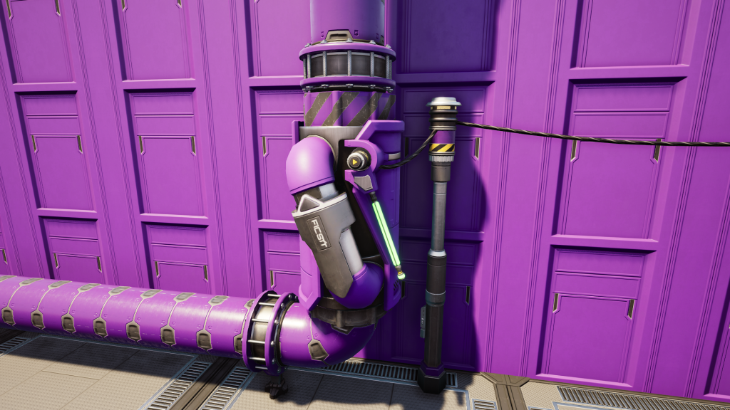
Pipeline Pumps are used to create more Head Lift and allow fluids to flow up vertically higher. Pumps require Power to work. Unpowered pumps remove all Head Lift, essentially stopping flow in both directions.
Powered functional pumps do not add to existing Head Lift; a pump will set the Head Lift for the output side to its level (20 or 50) regardless of the input Head Lift. Head Lift from the output side to the input side of a pump is zero (0), essentially acting as a Valve.
The actual amount of Head Lift produced by pumps is slightly more than the listed recommended Head Lift. However, the distance to the middle of the Pump is also considered in Head Lift calculation, so sticking with the recommended distance is, well, recommended.
There are two types of pumps that differ in Power required and Head Lift produced:
| Pump Name |
Power | Recommended Head Lift (Meters) |
Actual Head Lift (Meters) |
|---|---|---|---|
| Pipeline Pump Mk.1 | 4 MW | 20 Meters | 22 Meters |
| Pipeline Pump Mk.2 | 8 MW | 50 Meters | 55 Meters |
The only way to measure Head Lift is with Pipeline Pumps. These will show the current Head Lift at their location and the direction. They will show both the amount of Head Lift coming in and the amount of Head Lift going out.
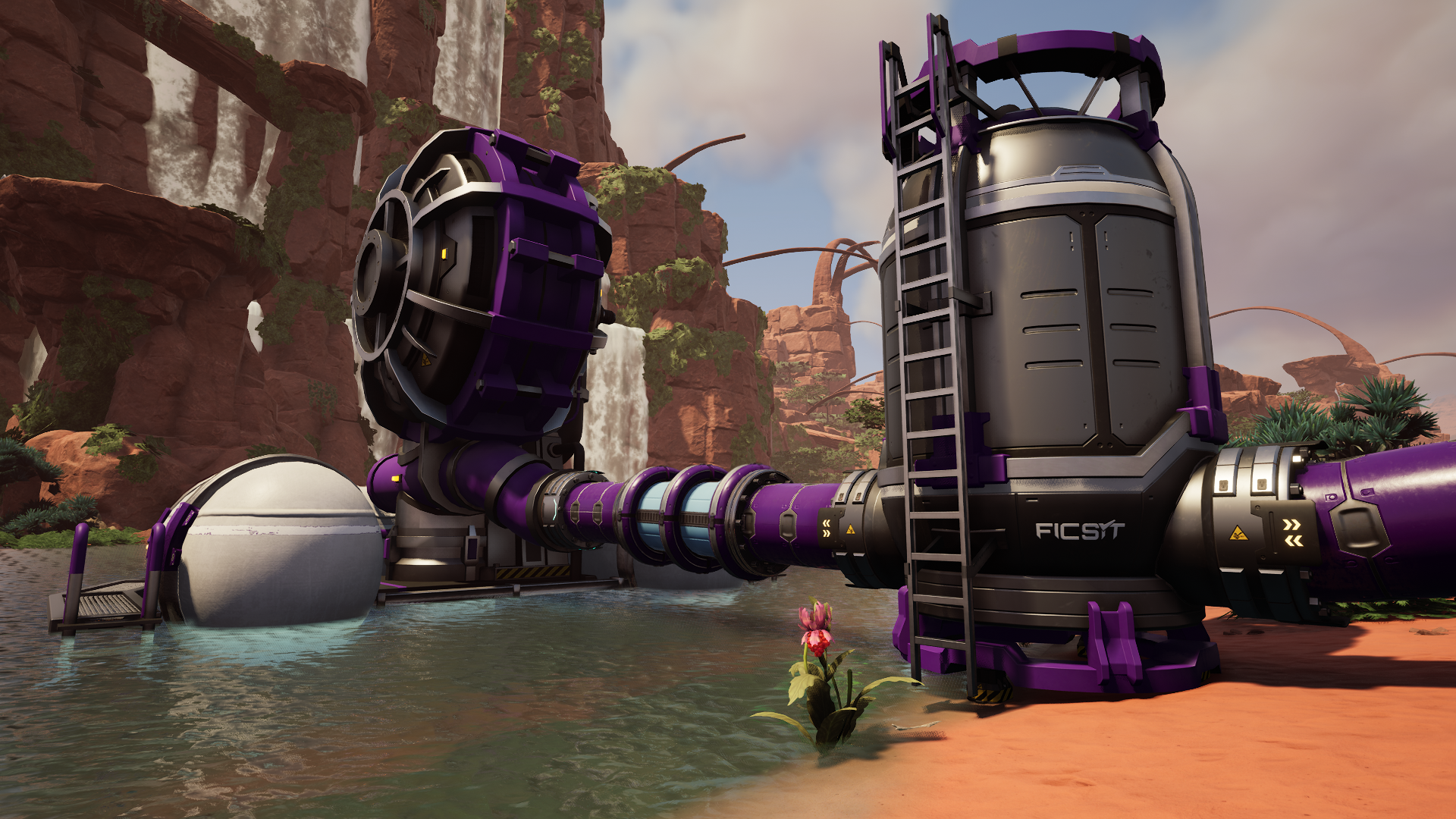
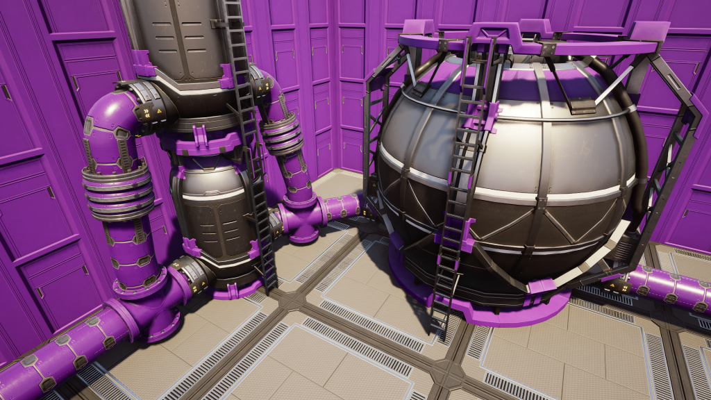
Fluid Buffer (Storage)
There are two options for storing fluids: Fluid Buffer and Industrial Fluid Buffer. They operate almost exactly the same, other than the difference in capacity and potential Head Lift. The Industrial version can hold six times as much liquid.
| Buffer Name | Capacity | Head Lift When Full |
|---|---|---|
| Fluid Buffer | 400 Cubic Meters | 8 Meters |
| Industrial Fluid Buffer |
2400 Cubic Meters | 12 Meters |
Buffers have Pipeline ports on two opposite sides. Neither port has a specific direction. Buffers that are at least partially filled create Head Lift in both ports, proportional to the percentage of total volume filled.
Like Pipelines, Fluid Buffers can be flushed. You can choose to delete either the fluid in the buffer itself, or all the fluid in the connecting system.
Trains
Trains can also be used to transport fluids with the use of Freight Cars. Freight cars can accept both items and fluids. While they take more effort to set up than other options, they are well worth the effort over long distances.
Check out the dedicated page for more on Trains.